6ES7155-6AR00-0AN0ET 200接口模块 6ES7155-6AR00-0AN0ET 200接口模块 6ES7155-6AR00-0AN0ET 200接口模块
由于功能十分丰富,可扩展的 ET 200SP I/O 系统的接口模块(即使是基本型号)可在广泛的应用中使用。这些接口模块的基本功能包括:
使用 PROFINET 接口模块时,还包括以下基本功能:
下面所列是可用于 ET 200SP 的接口模块的简略概览,显示了它们之间的基本差别。通过 TIA Selection Tool,可更加清晰和精确地比较不同接口模块的功能。
SIMATIC IM155-6DP 高性能型,带 PROFIBUS 连接
SIMATIC IM155-6PN 基本型,带 PROFINET 接口
SIMATIC IM155-6PN 标准型,带 PROFINET 接口
SIMATIC IM155-6PN 高性能型,带 PROFINET 接口
SIMATIC IM155-6PN 高转速型,带 PROFINET 接口
PROFINET IM 155-6PN 基本型接口模块
IM 155-6PN 标准型接口模块 (PROFINET)
IM 155-6PN 高性能型接口模块 (PROFINET)
IM 155-6DP 高性能型接口模块 (PROFIBUS)
IM 155-6PN 标准型接口模块可直接卡到标准安装导轨上。
IM 155-6PN 标准型具有:
可用型号:
Article number
6ES7155-6AR00-0AN0
6ES7155-6AA01-0BN0
6ES7155-6AU00-0BN0
6ES7155-6AU00-0CN0
6ES7155-6AU00-0DN0
6ES7155-6BA00-0CN0
ET 200SP, IM155-6PN BASIC
ET 200SP, IM155-6PN ST INCL. BA 2XRJ45
ET 200SP, IM155-6PN ST
ET 200SP, IM155-6PN HF
ET 200SP, IM155-6PN HS
ET 200SP, IM155-6DP HF INCL. DP-CONNECT.
General inbation
Product type designation
IM 155-6 PN BA
IM 155-6 PN ST
IM 155-6 PN ST
IM 155-6 PN HF
IM 155-6 PN HS
IM 155-6 DP HF
HW functional status
FS01
Firmware version
V3.2
V4.1
V3.3
V3.3
V4.0
V3.1
Product function
● I&M data
Yes; I&M0 to I&M3
Yes; I&M0 to I&M3
Yes; I&M0 to I&M3
Yes; I&M0 to I&M4
Yes; I&M0 to I&M3
Yes; I&M0 to I&M3
● Module swapping during operation (hot swapping)
Yes; Single hot swapping
Yes; Single hot swapping
Yes; Single hot swapping
Yes; Multi-hot swapping
Yes; Multi-hot swapping
Yes; Multi-hot swapping
Engineering with
● STEP 7 TIA Portal configurable/integrated as of version
V13 SP1
V14
V13 SP1
V13 SP1 Update 6
STEP 7 V14 or higher
V13 SP1
● STEP 7 configurable/integrated as of version
V5.5 SP4 and higher
V5.5 SP4 and higher
V5.5 SP4 and higher
V5.5 SP4 and higher
V5.5 SP4 and higher
V5.5 SP4 and higher
● PROFIBUS as of GSD version/GSD revision
One GSD file each, Revision 3 and 5 and higher
● PROFINET as of GSD version/GSD revision
V2.3 / -
V2.3 / -
V2.3 / -
- / V2.3
- / V2.3
Configuration control
via dataset
Yes
Yes
Yes
Yes
Yes
Yes
Supply voltage
Type of supply voltage
DC
Rated value (DC)
24 V
24 V
24 V
24 V
24 V
24 V
permissible range, lower limit (DC)
19.2 V
19.2 V
19.2 V
19.2 V
19.2 V
19.2 V
permissible range, upper limit (DC)
28.8 V
28.8 V
28.8 V
28.8 V
28.8 V
28.8 V
Reverse polarity protection
Yes
Yes
Yes
Yes
Yes
Yes
Short-circuit protection
Yes
Mains buffering
● Mains/voltage failure stored energy time
5 ms
10 ms
5 ms
5 ms
5 ms
5 ms
Input current
Current consumption (rated value)
450 mA
Current consumption, max.
300 mA
550 mA
450 mA
700 mA
500 mA
250 mA
Inrush current, max.
3.7 A
3.7 A
4.5 A
4.5 A
4.5 A
I²t
0.09 A²·s
0.09 A²·s
0.09 A²·s
0.09 A²·s
0.09 A²·s
Power
Infeed power to the backplane bus
4.5 W
Power loss
Power loss, typ.
1.8 W
1.9 W
1.9 W
2.4 W
1.7 W
1.5 W
Address area
Address space per module
● Address space per module, max.
32 byte; per b / output
256 byte; per b / output
256 byte; per b / output
288 byte; For b and output data respectively
32 byte; For b and output data respectively
32 byte; per b / output
Address space per station
● Address space per station, max.
32 byte; per b / output
512 byte; Dependent on configuration
512 byte; Dependent on configuration
1 440 byte; Dependent on configuration
968 byte; For b and output data respectively
244 byte; per b / output
Hardware configuration
Rack
● Modules per rack, max.
12
32; + 16 ET 200AL modules
32; + 16 ET 200AL modules
64; + 16 ET 200AL modules
30
32; + 16 ET 200AL modules
Submodules
● Number of submodules per station, max.
256
256
256
125
Interfaces
Number of PROFINET interfaces
1; 2 ports (switch)
1; 2 ports (switch)
1; 2 ports (switch)
1; 2 ports (switch)
1; 2 ports (switch)
Number of PROFIBUS interfaces
1
1. Interface
Interface types
● Number of ports
2
2
2
2
2
● integrated switch
Yes
Yes
Yes
Yes
Yes
● RJ 45 (Ethernet)
Yes; 2 integrated RJ45 ports
Yes; Pre-assembled BusAdapter BA 2x RJ45
● RS 485
Yes
● BusAdapter (PROFINET)
No
Yes; Applicable BusAdapter: BA 2x RJ45, BA 2x FC
Yes; Applicable BusAdapter: BA 2x RJ45, BA 2x FC
Yes; Compatible BusAdapter: BA 2x RJ45, BA 2x FC, BA 2x SCRJ (from FS03, V2.2), BA SCRJ / RJ45 (from FS03, V3.1), BA SCRJ / FC (from FS03, V3.1), BA 2x LC (from FS03, V3.3), BA LC / RJ45 (from FS03, V3.3), BA LC / FC (from FS03, V3.3)
Yes; Compatible BusAdapter: BA 2x RJ45, BA 2x FC, BA 2x SCRJ, BA SCRJ / RJ45, BA SCRJ / FC, BA 2x LC, BA LC / RJ45, BA LC / FC
● Output current of the interface, max.
90 mA
Functionality
● PROFINET IO Device
Yes
Yes
Yes
Yes
Yes
● PROFIBUS DP slave
Yes
● Open IE communication
Yes
Yes
Yes
Yes
Yes
● Media redundancy
Yes; PROFINET MRP
Yes; PROFINET MRP
Yes; PROFINET MRP
Yes; PROFINET MRP
Yes; As MRP or MRPD client; max. 50 or 30 devices in the ring
Interface types
RJ 45 (Ethernet)
● Transmission procedure
PROFINET with 100 Mbit/s full duplex (100BASE-TX)
PROFINET with 100 Mbit/s full duplex (100BASE-TX)
PROFINET with 100 Mbit/s full duplex (100BASE-TX)
PROFINET with 100 Mbit/s full duplex (100BASE-TX)
PROFINET with 100 Mbit/s full duplex (100BASE-TX)
● 10 Mbps
No
Yes; for Ethernet services
No
No
No
● 100 Mbps
Yes; PROFINET with 100 Mbit/s full duplex (100BASE-TX)
Yes; PROFINET with 100 Mbit/s full duplex (100BASE-TX)
Yes; PROFINET with 100 Mbit/s full duplex (100BASE-TX)
Yes; PROFINET with 100 Mbit/s full duplex (100BASE-TX)
Yes; PROFINET with 100 Mbit/s full duplex (100BASE-TX)
● Autonegotiation
Yes
Yes
Yes
Yes
Yes
● Autocrossing
Yes
Yes
Yes
Yes
Yes
RS 485
● Transmission rate, max.
12 Mbit/s
PROFINET IO Device
Services
— Isochronous mode
No
No
No
Yes; Bus cycle time: min. 250 µs
Yes; Bus cycle time: min. 125 µs
— Open IE communication
Yes
Yes
Yes
Yes
Yes
— IRT
No
Yes; with send cycles of between 250 µs and 4 ms in increments of 125 µs
Yes; with send cycles of between 250 µs and 4 ms in increments of 125 µs
Yes; 250 μs, 500 μs, 1 ms, 2 ms, 4 ms additionally with IRT with high perbance: 250 µs to 4 ms in 125 µs frame
Yes; 125 µs, 250 µs, 500 µs, 1 ms, 2 ms, 4 ms additionally with IRT with high perbance: 250 µs to 4 ms in 125 µs frame
— PROFIenergy
No
Yes
Yes
Yes
Yes
— Prioritized startup
No
Yes
Yes
Yes
Yes
— Shared device
No
Yes
Yes
Yes
Yes
— Number of IO Controllers with shared device, max.
2
2
4
4
Redundancy mode
— MRP
Yes
Yes
Yes
Yes
Yes
— MRPD
No
No
No
No
Yes
— PROFINET system redundancy (S2)
No
No
No
Yes; NAP S2
No
Open IE communication
● TCP/IP
Yes
Yes
Yes
Yes
Yes
● SNMP
Yes
Yes
Yes
Yes
Yes
● LLDP
Yes
Yes
Yes
Yes
Yes
PROFIBUS DP
Services
— SYNC capability
Yes
— FREEZE capability
Yes
— DPV0
Yes
— DPV1
Yes
Isochronous mode
Isochronous operation (application synchronized up to terminal)
No
No
No
Yes
Yes
No
Equidistance
No
No
Yes
Yes
shortest clock pulse
250 µs
125 µs
max. cycle
4 ms
4 ms
Bus cycle time (TDP), min.
250 µs
125 µs
Jitter, max.
1 µs
0.25 µs
Interrupts/diagnostics/status inbation
Status indicator
Yes
Yes
Yes
Yes
Yes
Yes
Alarms
Yes
Yes
Yes
Yes
Yes
Yes
Diagnostic functions
Yes
Yes
Yes
Yes
Yes
Yes
Diagnostics indication LED
● RUN LED
Yes; Green LED
Yes; Green LED
Yes; Green LED
Yes; Green LED
Yes; Green LED
Yes; Green LED
● ERROR LED
Yes; Red LED
Yes; Red LED
Yes; Red LED
Yes; Red LED
Yes; Red LED
Yes; Red LED
● MAINT LED
Yes; yellow LED
Yes; yellow LED
Yes; yellow LED
Yes; yellow LED
Yes; yellow LED
Yes; yellow LED
● Monitoring of the supply voltage (PWR-LED)
Yes; green PWR LED
Yes; green PWR LED
Yes; green PWR LED
Yes; green PWR LED
Yes; green PWR LED
Yes; green PWR LED
● Connection display LINK TX/RX
Yes; 2x green LED
Yes; 2x green b LEDs on BusAdapter
● Connection display DP
Yes; Green DP LED
● Connection to network LINK (green)
Yes; 2x green b LEDs on BusAdapter
Yes; 2x green b LEDs on BusAdapter
Yes; 2x green b LEDs on BusAdapter
Potential separation
between backplane bus and electronics
No
No
No
No
No
No
between PROFIBUS DP and all other circuit components
Yes
between PROFINET and all other circuits
Yes
Yes; 1500 V AC
Yes
Yes
Yes
between supply and all other circuits
No
No
Yes
Yes
No
Yes
Permissible potential difference
between different circuits
Safety extra low voltage SELV
75 V DC/60 V AC (base isolation)
Isolation
Isolation tested with
707 V DC (type test)
707 V DC between supply voltage and electronics; 1 500 V AC between Ethernet and electronics
707 V DC between supply voltage and electronics (type test); 1 500 V AC between Ethernet and electronics (type test)
707 V DC between supply voltage and electronics (type test); 1 500 V AC between Ethernet and electronics (type test)
707 V DC (type test)
Standards, approvals, certificates
Network loading class
2
2
2
3
3
Security level
According to Security Level 1 Test Cases V1.1.1
According to Security Level 1 Test Cases V1.1.1
According to Security Level 1 Test Cases V1.1.1
According to Security Level 1 Test Cases V1.1.1
Ambient conditions
Ambient temperature during operation
● horizontal installation, min.
0 °C
0 °C
0 °C
0 °C
0 °C
0 °C
● horizontal installation, max.
60 °C
60 °C
60 °C
60 °C
60 °C
60 °C
● vertical installation, min.
0 °C
0 °C
0 °C
0 °C
0 °C
0 °C
● vertical installation, max.
50 °C
50 °C
50 °C
50 °C
50 °C
50 °C
Connection b
ET-Connection
● via BU/BA Send
No
Yes; + 16 ET 200AL modules
Yes; + 16 ET 200AL modules
Yes; + 16 ET 200AL modules
No
Yes; + 16 ET 200AL modules
Dimensions
Width
35 mm
50 mm
50 mm
50 mm
50 mm
50 mm
Height
117 mm
117 mm
117 mm
117 mm
117 mm
117 mm
Depth
74 mm
74 mm
74 mm
74 mm
74 mm
74 mm
Weights
Weight, approx.
125 g
190 g; IM 155-6 PN BA with 2x RJ45 ports and server module
147 g; without BusAdapter
147 g; without BusAdapter
147 g; without BusAdapter
150 g
目录:
1 问题
1 问题
Normal 0 false false false false EN-US ZH-CN X-NONE
序号
说明与图示
1.
内部风冷
驱动组件中电子单元和功率单元产生的功率损耗通过自然冷却或强制通风系统排散到控制柜内部
2.
外部风冷
采用“穿孔”技术,系统组件中功率单元的散热器穿过控制柜内的安装面。因此可以将电力电路的热损耗释放到一个单独的外部冷却回路上,柜内残留的热损耗由电子元件产生。这种外部散热器可以达到IP54防护等级。散热器配有散热片和风扇(属于供货范围),向后伸出一个单独的通风管道,该管道也可以向外打开。
3.
冷却板式冷却
采用冷却板式冷却的单元可以将功率单元的热损耗通过单元后面板上的导热介质传导到一个外部散热器上。例如,外部散热器可采用水冷。
4.
液体冷却
在液冷单元,功率半导体安装在冷却介质流经的散热器上,该单元产生的大部分热量会被冷却介质吸收并可在控制柜外耗散。
以下手册中介绍了模块共享输入/输出(MSI/MSO)的基本信息。 SIMATIC PROFINET PROFINET with STEP 7 V13.
条目 ID 102325771包含了支持MSI/MSO功能的IO设备的概览。
这篇文档介绍了如何在STEP 7 (TIA Portal)中配置访问共享的设备及模块内部共享输入/输出功能。可以在两个不同的项目里或同一个项目里来配置IO 控制器。
按照以下步骤在同一个项目下配置两个CPU:
按照以下步骤在两个不同的项目下配置两个CPU:
图1.(RS485)和图2.(RS422)
图3.(RS485)和图4.(RS422)
图5.(RS485)和图6.(RS422)
图7.和图8.(RS485)
注意:
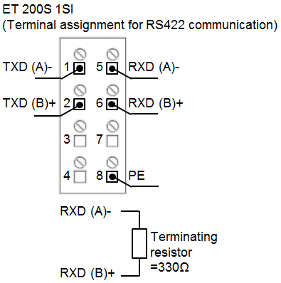
如果使用了超过 50m 的 RS485 连接线或 RS422 连接线,需要加约 330Ω 的终端电阻。
CM 1241 和 CB 1241 的模块使用其它的终端电阻。
终端和偏置在 RS485 网络的两端设置,中间的设备不需要增加终端和偏置。
ET200SP CM PtP
图1 .显示了 RS485 接口通讯的端子分配。
图 2.显示了 RS422 接口通讯的端子分配。
S7-1500 CM PtP RS485/RS422 BA/HF, CP 340,CP341,CP440, CP 441-1 和 CP 441-2 通讯模块的 RS485 和 RS422 接口连接
图 3.显示了 RS485 接口通讯的端子分配
图 4.显示了 RS422 接口通讯的端子分配
ET200S 1SI
使用 RS 485 公头连接器可以在一个 RS485 网络中连接多个设备,连接器可以在终端网络选择终端电阻。更多的信息参考下列链接中 S7-1200 手册的第13.2 章节。
连接终端电阻时,将 TRA 和 TA 短接,TRB 和 TB 短接。

列表价(不含增值税)
显示价格
您的单价(不含增值税)
显示价格
PDF 格式的数据表
下载
服务和支持 (手册,认证,问答...)
下载
产品
商品编号(市售编号)
6ES7155-6AR00-0AN0
产品说明
SIMATIC ET 200SP, PROFINET 接口模块 IM 155-6PN Basic, 最多 12 个周边模块, 2x 集成的 RJ45 插槽 包括服务器模块
产品家族
订货数据总览
产品生命周期 (PLM)
PM300:有效产品
价格数据
价格组 / 总部价格组
IR / 255
列表价(不含增值税)
显示价格
您的单价(不含增值税)
显示价格
金属系数
无
交付信息
出口管制规定
AL : N / ECCN : N
工厂生产时间
15 天
净重 (Kg)
0.243 Kg
产品尺寸 (W x L X H)
未提供
包装尺寸
8.30 x 12.20 x 6.30
包装尺寸单位的测量
CM
数量单位
1 件
包装数量
1
其他产品信息
EAN
4047623405603
UPC
804766155307
商品代码
85176200
LKZ_FDB/ CatalogID
ST76
产品组
4520
原产国
德国
Compliance with the substance restrictions according to RoHS directive
RoHS 合规开始日期: 2015.05.01
产品类别
A: 问题无关,即刻重复使用
电气和电子设备使用后的收回义务类别
没有电气和电子设备使用后回收的义务
分类
版本
分类
eClass
5.1
27-24-26-08
eClass
6
27-24-26-08
eClass
7.1
27-24-26-08
eClass
8
27-24-26-08
eClass
9
27-24-26-08
eClass
9.1
27-24-26-08
ETIM
5
EC001604
ETIM
6
EC001604
IDEA
4
3564
UNSPSC
14
32-15-17-05
UNSPSC
15
32-15-17-05

![]() 6ES7193-6BP00-0BA0
6ES7193-6BP00-0BA0

![]() 6ES7193-6BP00-0DA0
6ES7193-6BP00-0DA0

![]() 6ES7193-6BP20-0DA0
6ES7193-6BP20-0DA0

![]() 6ES7193-6BP20-0BA0
6ES7193-6BP20-0BA0

![]() 6ES7131-6BH01-0BA0
6ES7131-6BH01-0BA0
概述
![]()
应用
![]()
设计
![]()
技术规范
S120 书本型模块有哪些冷却方式
2 回答
S120 书本型模块有哪些冷却方式?
2 回答
SINAMICS S120 书本型模块提供了以下几种不同冷却方式的订货形式:
(1) 内部风冷
(2) 外部风冷
(3) 冷却板式冷却
(4) 液体冷却
各种冷却方式的详细说明如表1所示。


如何在STEP 7 (TIA Portal)中配置访问共享的设备及模块内部共享输入/输出(MSI/MSO)功能?
在这个例子里,一个S7-1500 CPU和一个S7-300 CPU作为IO控制器来访问作为共享设备的ET200SP的输入和输出数据。
一个输入模块和一个输出模块插到ET200SP的插槽中,S7-1500CPU将会读取输入和写入输出,S7-300CPU将会读取输入和输出。

图. 1
在同一个项目下的配置

图. 2

图. 3

图. 4
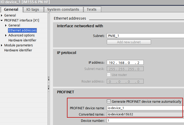
图. 5
在例子里S7-1500CPU会被设置为输出,也就是说S7-1500(PLC1)可以访问输出模块的输出,因此对于S7-1500来说输出模块是一个基本模块。因此对于S7-1500来说输入模块是一个MSI模块。
提供给S7-300 (PLC_2)数据的模块或它们的副本不会分配给其他的IO控制器,不要将接口模块分配给任何的IO控制器。
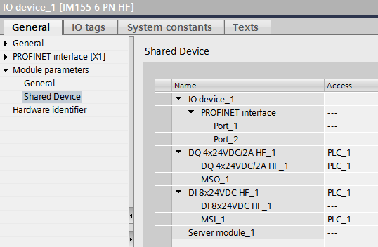
图. 6
在例子里S7-300CPU管理输出模块的输出副本,也就是说S7-300(PLC2)可以访问输出模块的输出副本,因此对于S7-300来说输出模块是一个MSO模块。
S7-300(PLC2)访问输入模块的输入,因此对于S7-300来说输入模块是一个基本模块。
提供给S7-1500 (PLC_1)数据的模块或它们的副本不会分配给其他的IO控制器,
不要将接口模块分配给任何的IO控制器。
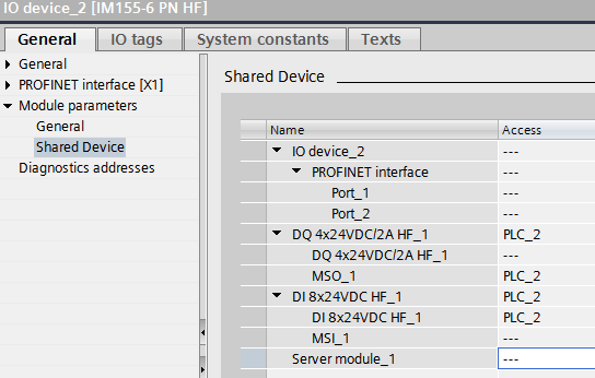
图. 7
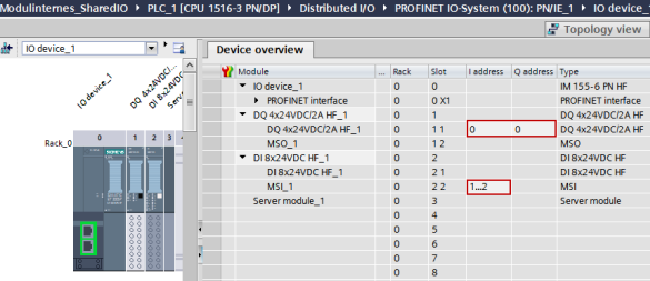
图. 8
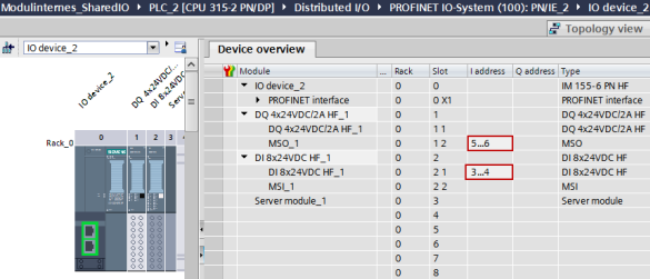
图. 9
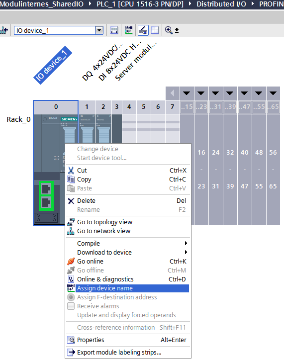
图. 10
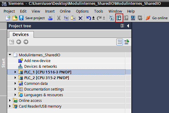
图. 11
在两个不同项目下的配置
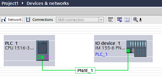
图. 12
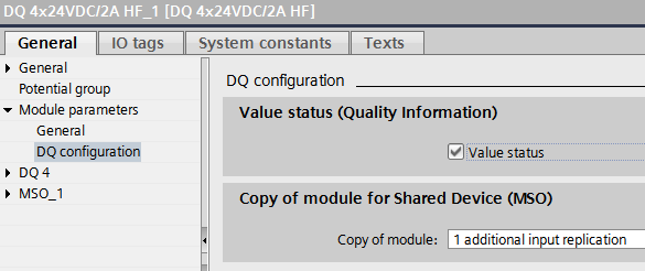
图. 13
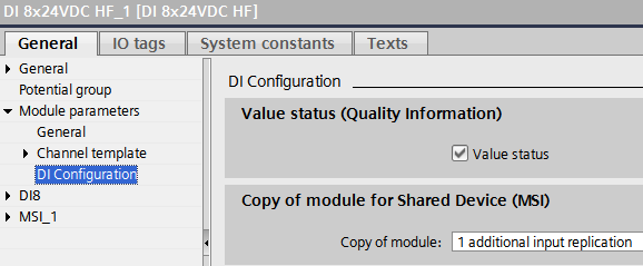
图. 14
在例子里 S7-1500CPU 会被设置为输出,也就是说S7-1500可以访问输出模块的输出,因此对于S7-1500来说输出模块是一个基本模块。
S7-1500访问输入模块的输入副本,因此对于S7-1500来说输入模块是一个MSI模块。
提供给S7-300数据的模块或它们的副本不会分配给其他的IO控制器。
不要将接口模块分配给任何的IO控制器。
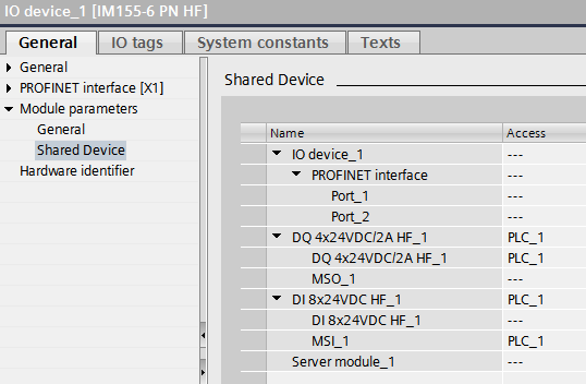
图. 15
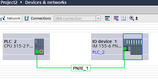
图. 16
在例子里S7-300 CPU管理输出模块的输出副本,也就是说 S7-300 可以访问输出模块的输出副本,因此对于 S7-300 来说输出模块是一个MSO模块。
S7-300访问输入模块的输入,因此对于S7-300来说输入模块是一个基本模块。
提供给S7-1500数据的模块或它们的副本不会分配给其他的IO控制器,
不要将接口模块分配给任何的IO控制器。
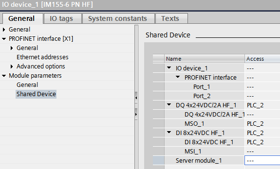
图. 17
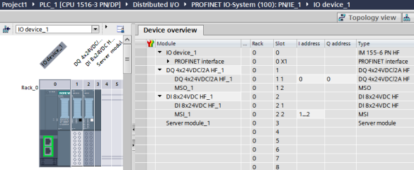
图. 18
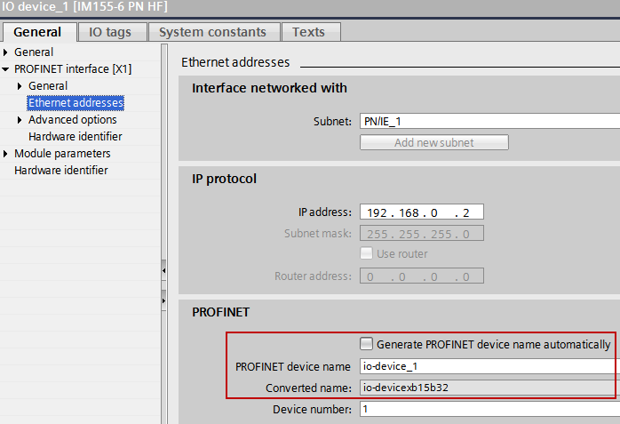
图. 19
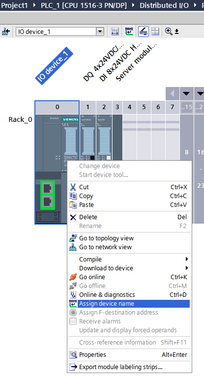
图. 20
怎样连接串口模块的 RS485/RS422 接口?
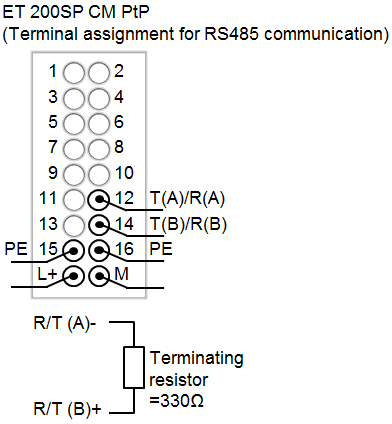
图. 1
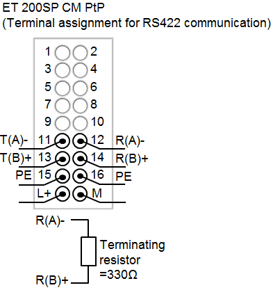
图. 2
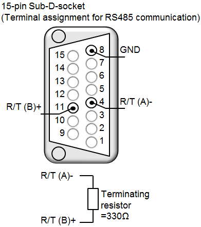
图. 3
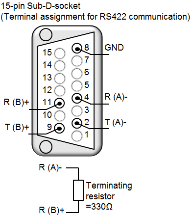
图. 4
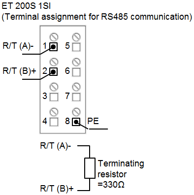
图. 5
CM1241
可以使用西门子9-针的 PROFIBUS DP 头连接 CM1241。
Fig. 7
CB 1241
CB1241 提供了内部的终端电阻,不具备 9-针的母 D 型连接器。
Fig. 8