长沙奈欧自动化设备有限公司专业销售西门子S7-200 / 300/400 / 1200PLC,数控系统,变频器,人机界面,触摸屏,伺服,电机,西门子电缆等,并可提供西门子维修服务,欢迎来电垂询
联系人: 刘文秀(销售经理)
24小时热线;137 6211 0473
QQ:1533714462
地址:长沙市岳麓区天顶街道尖山安置公寓楼702室
6ES7677-2FA41-0FB0西门子ET 200控制器 6ES7677-2FA41-0FB0西门子ET 200控制器 6ES7677-2FA41-0FB0西门子ET 200控制器
The ET 200SP Open Controller CPU 1515SP PC is a rugged, compact control system that combines the functionality of an ET 200SP controller with a PC-based platb. This means that the CPU offers the entire value added of the ET 200SP system, the fail-safe S7-1500 controller family and the TIA world combined. The controller can be used to control special and series machines, or to control systems in a distributed configuration. Using the fail-safe SIMATIC S7-1500 Software Controller allows processing of standard and safety programs on the same controller. Generation of the fail-safe and standard user program is carried out in the TIA Portal with the same editors. This integration makes the system benefits and comprehensive functionality of SIMATIC available for failsafe applications. The controller is especially suitable for machines with high data volumes, e.g. for quality assurance with camera inspection and image transmission, or printer connection. The CPU 1515SP PC F develops its full potential particularly when special automation functions are to be integrated using the programming languages C or C++, when a close connection of Windows software to the software controller is required, or when large volumes of data have to be stored.
The CPU 1515SP PC F + HMI with pre-installed WinCC Runtime Advanced is offered for additional HMI functionality. This enables control and visualization to be integrated on a single device.
The CPU 1515SP PC F is snapped directly onto the DIN rail like other ET 200SP CPUs. ET 200SP I/O modules can be plugged in directly and centrally, and they communicate via the integrated backplane bus. PN IO and S7 communication can be established and distributed I/Os can be connected via the PROFINET adapter of the ET 200SP system. This way, the system can be integrated into existing automation environments with little effort.
The PROFIBUS CM DP module extends the CPU 1515SP PC F to include PROFIBUS communication.
The following interfaces are available:
The CPU also features the following:
Different turnkey and pre-configured variants are available for various requirements:
Article number
6ES7677-2FA31-0EB0
6ES7677-2FA41-0FB0
CPU 1515SP PC F
CPU 1515SP PC F
General inbation
Product type designation
CPU 1515SP PC F
CPU 1515SP PC F
HW functional status
FS05
FS02
Firmware version
V2.1
V2.1
Engineering with
● STEP 7 TIA Portal configurable/integrated as of version
V14 SP1
V14 SP1
Installed software
● Visualization
No
No
● Control
S7-1500 Software Controller CPU 1505SP F
S7-1500 Software Controller CPU 1505SP F
Configuration control
via dataset
Yes
Yes
Control elements
Mode selector switch
1
1
Supply voltage
Type of supply voltage
24 V DC
24 V DC
permissible range, lower limit (DC)
19.2 V
19.2 V
permissible range, upper limit (DC)
28.8 V
28.8 V
Reverse polarity protection
Yes
Yes
Mains buffering
● Mains/voltage failure stored energy time
5 ms
5 ms
Input current
Current consumption (rated value)
1.5 A; Full processor load, incl. ET 200SP modules and using USB
1.5 A; Full processor load, incl. ET 200SP modules and using USB
Current consumption (in no-load operation), typ.
0.6 A
0.6 A
Inrush current, max.
4.7 A; Rated value
4.7 A; Rated value
Power
Active power b, max.
36 W; incl. ET 200SP modules and using USB
36 W; incl. ET 200SP modules and using USB
Infeed power to the backplane bus
8.75 W
8.75 W
Power loss
Power loss, typ.
15 W; without ET 200SP modules and without using USB
15 W; without ET 200SP modules and without using USB
Processor
Processor type
Dual-Core 1 GHz, AMD G Series APU T40E
Dual-Core 1 GHz, AMD G Series APU T40E
Memory
Type of memory
DDR3-SDRAM
DDR3-SDRAM
Main memory
4 GB RAM
4 GB RAM
CFast memory card
Yes; 30 GB flash memory
Yes; 30 GB flash memory
SIMATIC memory card required
No
No
Flash Disk
30 GB
30 GB
Work memory
● integrated (for program)
1.5 Mbyte
1.5 Mbyte
● integrated (for data)
5 Mbyte
5 Mbyte
● integrated (for CPU function library of CPU Runtime)
10 Mbyte
10 Mbyte
Load memory
● integrated (on PC mass storage)
320 Mbyte
320 Mbyte
Backup
● with UPS
Yes; all memory areas declared retentive
Yes; all memory areas declared retentive
● with non-volatile memory
Yes
Yes
CPU processing times
for bit operations, typ.
10 ns
10 ns
for word operations, typ.
12 ns
12 ns
for fixed point arithmetic, typ.
16 ns
16 ns
for floating point arithmetic, typ.
64 ns
64 ns
CPU-blocks
Number of elements (total)
6 000; In addition to blocks such as DBs, FBs and FCs, UDTs, b constants, etc. are also regarded as elements
6 000; In addition to blocks such as DBs, FBs and FCs, UDTs, b constants, etc. are also regarded as elements
DB
● Number, max.
5 999; Number range: 1 to 65535
5 999; Number range: 1 to 65535
● Size, max.
5 Mbyte
5 Mbyte
FB
● Number, max.
5 998; Number range: 1 to 65535
5 998; Number range: 1 to 65535
● Size, max.
512 kbyte
512 kbyte
FC
● Number, max.
5 999; Number range: 1 to 65535
5 999; Number range: 1 to 65535
● Size, max.
512 kbyte
512 kbyte
OB
● Size, max.
1 048 kbyte
512 kbyte
● Number of free cycle OBs
100
100
● Number of time alarm OBs
20
20
● Number of delay alarm OBs
20
20
● Number of cyclic interrupt OBs
20
20
● Number of process alarm OBs
50
50
● Number of DPV1 alarm OBs
3
3
● Number of isochronous mode OBs
1
1
● Number of technology synchronous alarm OBs
2
2
● Number of startup OBs
100
100
● Number of asynchronous error OBs
4
4
● Number of synchronous error OBs
2
2
● Number of diagnostic alarm OBs
1
1
Nesting depth
● per priority class
24; Up to 8 possible for F-blocks
24; Up to 8 possible for F-blocks
Counters, timers and their retentivity
S7 counter
● Number
2 048
2 048
Retentivity
— adjustable
Yes
Yes
IEC counter
● Number
Any (only limited by the main memory)
Any (only limited by the main memory)
Retentivity
— adjustable
Yes
Yes
S7 times
● Number
2 048
2 048
Retentivity
— adjustable
Yes
Yes
IEC timer
● Number
Any (only limited by the main memory)
Any (only limited by the main memory)
Retentivity
— adjustable
Yes
Yes
Data areas and their retentivity
Retentive data area (incl. timers, counters, flags), max.
410 kbyte; For storage in NVRAM; for storage in mass storage 5 242 020 bytes
410 kbyte; For storage in NVRAM; for storage in mass storage 5 242 020 bytes
Flag
● Number, max.
16 kbyte
16 kbyte
● Number of clock memories
8; 8 clock memory bits, grouped into one clock memory byte
8; 8 clock memory bits, grouped into one clock memory byte
Data blocks
● Retentivity adjustable
Yes
Yes
● Retentivity preset
No
No
Local data
● per priority class, max.
64 kbyte; max. 16 KB per block
64 kbyte; max. 16 KB per block
Address area
Number of IO modules
8 192
8 192
I/O address area
● Inputs
32 kbyte; All bs are in the process image
32 kbyte; All bs are in the process image
● Outputs
32 kbyte; All outputs are in the process image
32 kbyte; All outputs are in the process image
of which per assigned PC interface
— Inputs (volume)
8 kbyte
8 kbyte
— Outputs (volume)
8 kbyte
8 kbyte
Subprocess images
● Number of subprocess images, max.
32
32
Hardware configuration
Integrated power supply
Yes
Yes
Number of distributed IO systems
20
20
Number of DP masters
● Via CM
1
1
Rack
● Modules per rack, max.
64; CPU 1515SP PC + 64 modules + server module
64; CPU 1515SP PC + 64 modules + server module
● Number of lines, max.
1
1
PtP CM
● Number of PtP CMs
the number of connectable PtP CMs is only limited by the number of available slots
the number of connectable PtP CMs is only limited by the number of available slots
Time of day
Clock
● Type
Hardware clock
Hardware clock
● Hardware clock (real-time)
Yes; Resolution: 1 s
Yes; Resolution: 1 s
● Backup time
6 wk; At 40 °C ambient temperature, typically
6 wk; At 40 °C ambient temperature, typically
● Deviation per day, max.
10 s; Typ.: 2 s
10 s; Typ.: 2 s
Clock synchronization
● supported
Yes
Yes
● to DP, master
No
No
● on Ethernet via NTP
Yes
Yes
● on Windows clock, slave
Yes
Yes
Interfaces
Number of industrial Ethernet interfaces
2
2
Number of PROFINET interfaces
1
1
Number of PROFIBUS interfaces
1
1
Number of RS 485 interfaces
1; Via CM DP module
1; Via CM DP module
Number of USB interfaces
3; 3x USB 2.0 on the front, 500 mA each – of which 2x 500 mA and 1x 100 mA simultaneously
3; 3x USB 2.0 on the front, 500 mA each – of which 2x 500 mA and 1x 100 mA simultaneously
Number of SD card slots
1
1
Video interfaces
● Graphics interface
1x DVI-I
1x DVI-I
1. Interface
Interface type
PROFINET
PROFINET
automatic detection of transmission rate
Yes
Yes
Autonegotiation
Yes
Yes
Autocrossing
Yes
Yes
Interface types
● Number of ports
2
2
● integrated switch
Yes
Yes
● RJ 45 (Ethernet)
Yes; Via BusAdapter BA 2x RJ45
Yes; Via BusAdapter BA 2x RJ45
— Transmission rate, max.
100 Mbit/s
100 Mbit/s
— Industrial Ethernet status LED
Yes
Yes
● BusAdapter (PROFINET)
Yes; Applicable BusAdapter: BA 2x RJ45, BA 2x FC
Yes; Applicable BusAdapter: BA 2x RJ45, BA 2x FC
Functionality
● Number of connections via this interface
88
88
● PROFINET IO Controller
Yes
Yes
● PROFINET IO Device
Yes
Yes
● SIMATIC communication
Yes
Yes
● Open IE communication
Yes
Yes
● Web server
Yes
Yes
PROFINET IO Controller
Services
— Isochronous mode
Yes
Yes
— shortest clock pulse
500 µs
500 µs
— IRT
Yes
Yes
— MRP
Yes
Yes
— MRPD
Yes
Yes
— Prioritized startup
Yes; Max. 32 PROFINET devices
Yes; Max. 32 PROFINET devices
— Number of connectable IO Devices, max.
128
128
— Of which IO devices with IRT, max.
64
64
— of which in line, max.
64
64
— Number of connectable IO Devices for RT, max.
128
128
— of which in line, max.
128
128
— Number of IO Devices that can be simultaneously activated/deactivated, max.
8
8
— IO Devices changing during operation (partner ports), supported
Yes
Yes
— Number of IO Devices per tool, max.
8
8
— Updating times
The minimum value of the update time also depends on communication share set for PROFINET IO, on the number of IO devices, and on the quantity of configured user data
The minimum value of the update time also depends on communication share set for PROFINET IO, on the number of IO devices, and on the quantity of configured user data
Update time for IRT
— for send cycle of 500 µs
500 µs to 8 ms
500 µs to 8 ms
— for send cycle of 1 ms
1 ms to 16 ms
1 ms to 16 ms
— for send cycle of 2 ms
2 ms to 32 ms
2 ms to 32 ms
— for send cycle of 4 ms
4 ms to 64 ms
4 ms to 64 ms
— With IRT and beterization of "odd" send cycles
Update time = set "odd" send clock (any multiple of 125 µs: 375 µs, 625 µs ... 3 875 µs)
Update time = set "odd" send clock (any multiple of 125 µs: 375 µs, 625 µs ... 3 875 µs)
Update time for RT
— for send cycle of 500 µs
500 µs to 256 ms
500 µs to 256 ms
— for send cycle of 1 ms
1 ms to 512 ms
1 ms to 512 ms
— for send cycle of 2 ms
2 ms to 512 ms
2 ms to 512 ms
— for send cycle of 4 ms
4 ms to 512 ms
4 ms to 512 ms
PROFINET IO Device
Services
— Isochronous mode
No
No
— IRT
Yes
Yes
— MRP
Yes
Yes
— MRPD
Yes
Yes
— Prioritized startup
Yes
Yes
— Shared device
Yes
Yes
— Number of IO Controllers with shared device, max.
4
4
2. Interface
Interface type
Integrated Ethernet interface
Integrated Ethernet interface
automatic detection of transmission rate
Yes
Yes
Autonegotiation
Yes
Yes
Autocrossing
Yes
Yes
Interface types
● Number of ports
1
1
● RJ 45 (Ethernet)
Yes; Integrated
Yes; Integrated
— Transmission rate, max.
1 000 Mbit/s
1 000 Mbit/s
— Industrial Ethernet status LED
No
No
3. Interface
Interface type
PROFIBUS with CM DP
PROFIBUS with CM DP
Interface types
● RS 485
Yes
Yes
Functionality
● Number of connections via this interface
44
44
● PROFIBUS DP master
Yes
Yes
● PROFIBUS DP slave
Yes
Yes
● SIMATIC communication
Yes
Yes
DP master
● Number of DP slaves, max.
125
125
Services
— Equidistance
No
No
— Isochronous mode
No
No
DP slave
Services
— Equidistance
No
No
— Isochronous mode
No
No
RS 485
● Transmission rate, max.
12 Mbit/s
12 Mbit/s
Protocols
Number of connections
● Number of connections, max.
88
88
● Number of connections reserved for ES/HMI/web
10
10
● Number of S7 routing paths
16
16
SIMATIC communication
● PG/OP communication
Yes
Yes
● S7 routing
Yes
Yes
● S7 communication, as server
Yes
Yes
● S7 communication, as client
Yes
Yes
● User data per job, max.
64 kbyte
64 kbyte
Open IE communication
● TCP/IP
Yes
Yes
— Data length, max.
64 kbyte
64 kbyte
● ISO-on-TCP (RFC1006)
Yes
Yes
— Data length, max.
64 kbyte
64 kbyte
● UDP
Yes
Yes
— Data length, max.
1 472 kbyte
1 472 kbyte
● SNMP
Yes
Yes
● DCP
Yes
Yes
● LLDP
Yes
Yes
Web server
● HTTP
Yes; Via Windows and PROFINET interface
Yes; Via Windows and PROFINET interface
● HTTPS
Yes; Only via PROFINET interface
Yes; Only via PROFINET interface
OPC UA
● OPC UA Client
No
● OPC UA Server
Data access (read, write, subscribe), runtime license required
Yes; Data access (read, write, subscribe), runtime license required
— Application authentication
Available security policies: None, Basic128Rsa15, Basic256Rsa15, Basic256Sha256
Yes; Available security policies: None, Basic128Rsa15, Basic256Rsa15, Basic256Sha256
— Security policies
Available security policies: None, Basic128Rsa15, Basic256Rsa15, Basic256Sha256
Yes; Available security policies: None, Basic128Rsa15, Basic256Rsa15, Basic256Sha256
— User authentication
"anonymous" or by user name & password
Yes; "anonymous" or by user name & password
Further protocols
● MODBUS
Yes; MODBUS TCP
Yes; MODBUS TCP
Media redundancy
● Switchover time on line break, typ.
200 ms
200 ms
● Number of stations in the ring, max.
50
50
S7 message functions
Number of login stations for message functions, max.
32
32
Program alarms
Yes
Yes
Number of configurable program alarms
10 000
10 000
Number of simultaneously active program alarms
● Number of program alarms
1 000
1 000
● Number of alarms for system diagnostics
200
200
● Number of alarms for motion technology bs
160
160
Test commissioning functions
Joint commission (Team Engineering)
Yes; Parallel online access possible for up to 8 engineering systems
Yes; Parallel online access possible for up to 8 engineering systems
Status block
Yes; up to 8 simultaneously
Yes; up to 8 simultaneously
Single step
No
No
Status/control
● Status/control variable
Yes
Yes
● Variables
Inputs, outputs, memory bits, DB, times, counters
Inputs, outputs, memory bits, DB, times, counters
● Number of variables, max.
— of which status variables, max.
200
200
— of which control variables, max.
200
200
Forcing
● Forcing
Yes
Yes
● Forcing, variables
Inputs, outputs
Inputs, outputs
● Number of variables, max.
200
200
Diagnostic buffer
● present
Yes
Yes
● Number of entries, max.
1 000
1 000
— of which powerfail-proof
300
300
Traces
● Number of configurable Traces
4
4
● Memory size per trace, max.
512 kbyte
512 kbyte
Interrupts/diagnostics/status inbation
Diagnostics indication LED
● RUN/STOP LED
Yes
Yes
● ERROR LED
Yes
Yes
● MAINT LED
Yes
Yes
Supported technology bs
Motion Control
Yes
Yes
● Number of available Motion Control resources for technology bs (except cam disks)
2 400
2 400
● Required Motion Control resources
— per speed-controlled axis
40; per axis
40; per axis
— per bing axis
80; per axis
80; per axis
— per synchronous axis
160; per axis
160; per axis
— per external encoder
80; per external encoder
80; per external encoder
— per output cam
20; per cam
20; per cam
— per cam track
160; per cam track
160; per cam track
— per probe
40; per probe
40; per probe
● Positioning axis
— Number of bing axes at motion control cycle of 4 ms (typical value)
5
5
— Number of bing axes at motion control cycle of 8 ms (typical value)
12
12
Controller
● PID_Compact
Yes; Universal PID controller with integrated optimization
Yes; Universal PID controller with integrated optimization
● PID_3Step
Yes; PID controller with integrated optimization for valves
Yes; PID controller with integrated optimization for valves
● PID-Temp
Yes; PID controller with integrated optimization for temperature
Yes; PID controller with integrated optimization for temperature
Counting and measuring
● High-speed counter
Yes
Yes
EMC
Emission of radio interference acc. to EN 55 011
● Limit class A, for use in industrial areas
Yes
Yes
Standards, approvals, certificates
CE mark
Yes
Yes
CSA approval
Yes
Yes
cULus
Yes
Yes
FM approval
Yes
Yes
RCM (berly C-TICK)
Yes
Yes
Highest safety class achievable in safety mode
Probability of failure (for service life of 20 years and repair time of 100 hours)
— Low demand mode: PFDavg in accordance with SIL3
< 2.00E-05
< 2.00E-05
— High demand/continuous mode: PFH in accordance with SIL3
< 1.00E-09 1/h
< 1.00E-09 1/h
Ambient conditions
Ambient temperature during operation
● min.
0 °C
0 °C
● max.
Up to 60 °C with max. 32 ET 200SP modules and 3x 100 mA USB load; up to 55 °C with max. 64 ET 200SP modules and 2x max. 500 mA and 1x max. 100 mA USB load
Up to 60 °C with max. 32 ET 200SP modules and 3x 100 mA USB load; up to 55 °C with max. 64 ET 200SP modules and 2x max. 500 mA and 1x max. 100 mA USB load
● horizontal installation, min.
0 °C
0 °C
● horizontal installation, max.
60 °C
60 °C
● vertical installation, min.
0 °C
0 °C
● vertical installation, max.
50 °C; With max. 32 ET 200SP modules and 3x 100 mA USB load
50 °C; With max. 32 ET 200SP modules and 3x 100 mA USB load
Ambient temperature during storage/transportation
● min.
-40 °C
-40 °C
● max.
70 °C
70 °C
Vibrations
● Operation, tested according to IEC 60068-2-6
Yes
Yes
● Transport, tested acc. to IEC 60068-2-6
Yes
Yes
Shock testing
● tested according to IEC 60068-2-6
Yes
Yes
● tested according to IEC 60068-2-27
Yes
Yes
● tested according to IEC 60068-2-29
Yes
Yes
● Storage/transport, tested acc. to IEC 60068-2-27
Yes
Yes
Operating systems
Operating systems
Windows Embedded Standard 7 E 32-bit
Windows Embedded Standard 7 P 64-bit
Configuration
Programming
Programming language
— LAD
Yes; incl. failsafe
Yes; incl. failsafe
— FBD
Yes; incl. failsafe
Yes; incl. failsafe
— STL
Yes
Yes
— SCL
Yes
Yes
— CFC
No
No
— GRAPH
Yes
Yes
Know-how protection
● User program protection/password protection
Yes
Yes
● Copy protection
Yes
Yes
● Block protection
Yes
Yes
Access protection
● Protection level: Write protection
Yes
Yes
● Protection level: Read/write protection
Yes
Yes
● Protection level: Complete protection
Yes
Yes
Cycle time monitoring
● lower limit
adjustable minimum cycle time
adjustable minimum cycle time
● upper limit
adjustable maximum cycle time
adjustable maximum cycle time
Open Development interfaces
● Size of ODK SO file, max.
3.8 Mbyte
3.8 Mbyte
Peripherals/Options
Peripherals
● SD card
Optionally for additional mass storage
Optionally for additional mass storage
Dimensions
Width
160 mm
160 mm
Height
117 mm
117 mm
Depth
75 mm
75 mm
Weights
Weight, approx.
0.83 kg
0.83 kg
固件版本为V1.0或更高的"TM Count 1x24V" 和 "TM PosInput 1" 模块可以在以下ET 200SP接口模块下使用:
工艺模块支持以下列出的操作模式:
注意
警告
该常问问题仅适用于 STEP 7 (TIA Portal) V13 以及更高版本,因为版本低于 V13 的STEP7 的工艺对象是无法使用的。
表1显示了总线模块,模块还有DP/PA Link模块以及Y Link模块的可能组合。
表1
1) 在使用旧的CP 443-5 时(文章编号: 6GK7443-5DX02-0XE0), 在自动化系统中执行 IM 157/IM 153-2 只能在总线模块6ES7-7HE80-0XA0以及配置6ES70AA81-0XA0结合时操作。
表2 展示的是总线模块,模块(PROFIBUS IM 153-2)和配置ET 200M的可能组合。
表 2
表3 展示的是总线模块,模块(PROFIBUS IM 153-2 FO)和配置ET 200M的可能组合。
表 3
表 4 显示的是哪个总线模块可以使用接口模块PROFIBUS IM153-1。
表 4
表5显示的是哪个总线模块可以使用接口模块IM 153-4。
表 5
以下手册中介绍了模块共享输入/输出(MSI/MSO)的基本信息。 SIMATIC PROFINET PROFINET with STEP 7 V13.
条目 ID 102325771包含了支持MSI/MSO功能的IO设备的概览。
这篇文档介绍了如何在STEP 7 (TIA Portal)中配置访问共享的设备及模块内部共享输入/输出功能。可以在两个不同的项目里或同一个项目里来配置IO 控制器。
按照以下步骤在同一个项目下配置两个CPU:
按照以下步骤在两个不同的项目下配置两个CPU:

列表价(不含增值税)
显示价格
您的单价(不含增值税)
显示价格
PDF 格式的数据表
下载
服务和支持 (手册,认证,问答...)
下载
产品
商品编号(市售编号)
6ES7677-2FA41-0FB0
产品说明
SIMATIC ET 200SP Open 控制器,CPU 1515SP PC F. 4 GB RAM, 30 GB CFAST 带有 预装 WES 7 P 64 Bit, 带有 S7-1500 破损安全 SWC 预装 CPU 1505SP F 接口: 1个 CFAST 插槽,1个 SD/MMC 插槽, 1个接口,用于 ET 200SP 总线 适配器 PROFINET, 1个 10/100/1000 MBit/s 以太网 , 3个 USB, 1个 DVI-I 图像卡接口, 文档在 DVD 上, 恢复盘 DVD
产品家族
CPU 1515SP PC (F)
产品生命周期 (PLM)
PM300:有效产品
价格数据
价格组 / 总部价格组
JC / 216
列表价(不含增值税)
显示价格
您的单价(不含增值税)
显示价格
金属系数
无
交付信息
出口管制规定
AL : N / ECCN : 5D992
工厂生产时间
20 天
净重 (Kg)
0.83 Kg
产品尺寸 (W x L X H)
未提供
包装尺寸
14.20 x 18.90 x 9.20
包装尺寸单位的测量
CM
数量单位
1 件
包装数量
1
其他产品信息
EAN
4047623407959
UPC
804766556630
商品代码
85371091
LKZ_FDB/ CatalogID
STWINAC
产品组
4A72
原产国
德国
Compliance with the substance restrictions according to RoHS directive
RoHS 合规开始日期: 2016.12.16
产品类别
A: 问题无关,即刻重复使用
电气和电子设备使用后的收回义务类别
没有电气和电子设备使用后回收的义务
分类
版本
分类
eClass
5.1
27-24-26-07
eClass
6
27-24-26-07
eClass
7.1
27-24-26-07
eClass
8
27-24-26-07
eClass
9
27-24-26-07
eClass
9.1
27-24-26-07
ETIM
5
EC001603
ETIM
6
EC001603
IDEA
4
3565
UNSPSC
15
32-15-17-05

![]() 6ES7193-6BP00-0BA0
6ES7193-6BP00-0BA0

![]() 6ES7193-6BP00-0DA0
6ES7193-6BP00-0DA0

![]() 6ES7193-6BP20-0BA0
6ES7193-6BP20-0BA0

![]() 6ES7193-6BP20-0DA0
6ES7193-6BP20-0DA0

![]() 6AV2105-0FA04-0AA0
6AV2105-0FA04-0AA0
概述
For separating Windows systems from control functions
![]()
应用
![]()
设计
![]()
功能
SCL (IL), LAD, FBD, STL, GRAPH7 (SFC)
The real-time system of the integrated S7-1500 software controllers enables parallel, independent operation of Windows:
The CPU 1515SP PC F ensures the security of plant data even when the power fails:
PROFINET IO RT/IRT, isochronous mode, IO controller, I-device, media redundancy, PROFIenergy, PROFIBUS DP master
Scanning the CPU via the web server is supported by all CPUs of the S7‑1500 automation system. The CPU web server offers the following diagnostics options:
The trace function is supported by all CPUs of the S7-1500 automation system. It enables recording of analog and digital variables for each cycle and their representation as a curve with STEP 7. This is especially useful for motion control or closed-loop control applications
Universal PID or 3-step controller with integrated optimization. Integrated temperature controller.
System diagnostics can be displayed via a connected monitor, an HMI device, the web server, or the operator panel of the software controller. Drive messages are also displayed in this way. System diagnostics are also available when the CPU is in STOP mode. If new hardware components are configured, the diagnostic inbation is updated automatically.
Algorithms and program blocks can be reliably password-protected against unauthorized access and modification.
Extended access protection provides comprehensive protection against unauthorized configuration changes. Various authorization levels are available for assigning separate rights to different user groups.
The system protects the data transferred to the CPU against unauthorized tampering. Modified or third-party transmission of engineering data are safely detected by the CPU.
![]()
技术规范
哪些接口模块和ET 200SP的CPU可以使用 "TM Count 1x24V" 和 "TM PosInput 1" 模块?
哪些总线模块是可以和ET 200M接口模块一起使用的?
总线模块
IM 157
模块 IM 157
模块 IM 153-2
配置/功能
6ES7157-0AA81-0XA0
6ES7157-0AA82-0XA0
6ES7153-2BA81-0XB0
6ES7153-2BA82-0XB0
6ES7153-2BA70-0XB0
6ES7195-7HE80-0XA0
是1)
是1)
是1)
是1)
否
6ES7157-0AA81-0XA0
6ES7195-7HD80-0XA0
否
是
是
是
否
6ES7157-0AA82-0XA0
否
否
是
是
是
6ES7153-2BA81-0XA0 及更高
总线模块
IM 153-2
IM 153-2 HF
配置/功能
6ES7153-2AA02-0XB0
6ES7153-2BA00-0XB0
6ES7153-2BA01-0XB0
6ES7153-2BA02-0XB0
6ES7153-2BA10-0XB0
6ES7195-7HA00-0XA0
是
是
是
是
是
6ES7153-2AA02-0XB0
否
是
是
是
是
6ES7153-2BA00-0XB0 及更高
6ES7195-7HD00-0XA0
是
是
是
是
否
6ES7153-2AA02-0XB0
6ES7195-7HD10-0XA0
否
是
是
是
是
6ES7153-2AA02-0XB0
否
是
是
是
是
6ES7153-2BA00-0XB0 及更高
总线模块
IM 153-2 FO
IM 153-2 FO HF
配置/功能
6ES7153-2AB00-0XB0
6ES7153-2AB01-0XB0
6ES7153-2BB00-0XB0
6ES7195-7HA00-0XA0
是
是
是
6ES7153-2AB00-0XB0
否
是
是
6ES7153-2AB01-0XB0
否
否
是
6ES7153-2BB00-0XB0
6ES7195-7HD00-0XA0
是
是
是
6ES7153-2AB00-0XB0
否
是
是
6ES7153-2AB01-0XB0
6ES7195-7HD10-0XA0
否
否
是
6ES7153-2AB00-0XB0
否
否
是
6ES7153-2AB01-0XB0
否
否
是
6ES7153-2BB00-0XB0
总线模块
IM 153-1
6ES7153-1AA00-0XB0
6ES7153-1AA01-0XB0
6ES7153-1AA02-0XB0
6ES7153-1AA03-0XB0
6ES7153-1AA82-0XB0
6ES7153-1AA83-0XB0
6ES7195-7HA00-0XA0
是
是
是
是
是
是
6ES7195-7HD00-0XA0
否
否
否
否
否
否
6ES7195-7HD10-0XA0
否
否
否
否
否
否
总线模块
IM 153-4 PN
IM 153-4 PN HF
6ES7153-4AA00-0XB0
6ES7153-4AA00-0XB0
6ES7153-4BA00-0XB0
6ES7195-7HA00-0XA0
是
是
是
6ES7195-7HD00-0XA0
否
否
否
6ES7195-7HD10-0XA0
否
否
否
如何在STEP 7 (TIA Portal)中配置访问共享的设备及模块内部共享输入/输出(MSI/MSO)功能?
在这个例子里,一个S7-1500 CPU和一个S7-300 CPU作为IO控制器来访问作为共享设备的ET200SP的输入和输出数据。
一个输入模块和一个输出模块插到ET200SP的插槽中,S7-1500CPU将会读取输入和写入输出,S7-300CPU将会读取输入和输出。

图. 1
在同一个项目下的配置

图. 2

图. 3

图. 4
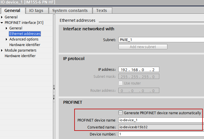
图. 5
在例子里S7-1500CPU会被设置为输出,也就是说S7-1500(PLC1)可以访问输出模块的输出,因此对于S7-1500来说输出模块是一个基本模块。因此对于S7-1500来说输入模块是一个MSI模块。
提供给S7-300 (PLC_2)数据的模块或它们的副本不会分配给其他的IO控制器,不要将接口模块分配给任何的IO控制器。
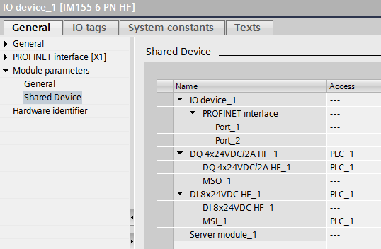
图. 6
在例子里S7-300CPU管理输出模块的输出副本,也就是说S7-300(PLC2)可以访问输出模块的输出副本,因此对于S7-300来说输出模块是一个MSO模块。
S7-300(PLC2)访问输入模块的输入,因此对于S7-300来说输入模块是一个基本模块。
提供给S7-1500 (PLC_1)数据的模块或它们的副本不会分配给其他的IO控制器,
不要将接口模块分配给任何的IO控制器。
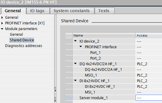
图. 7
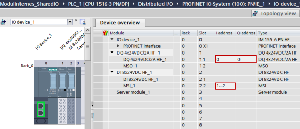
图. 8
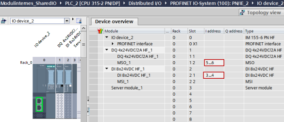
图. 9
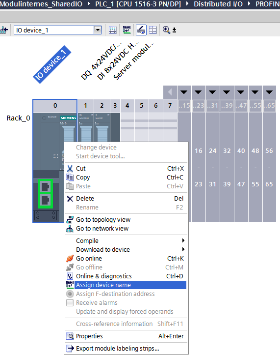
图. 10
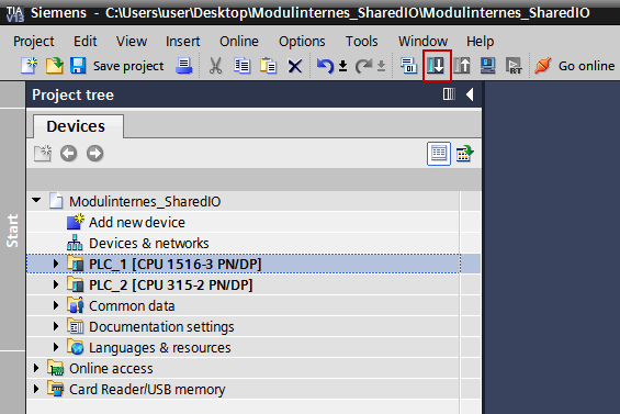
图. 11
在两个不同项目下的配置
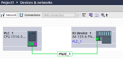
图. 12
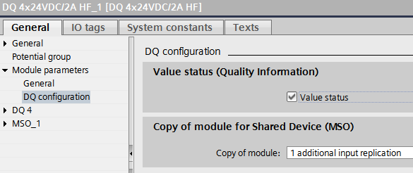
图. 13
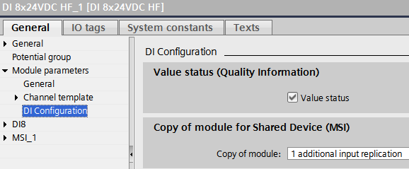
图. 14
在例子里 S7-1500CPU 会被设置为输出,也就是说S7-1500可以访问输出模块的输出,因此对于S7-1500来说输出模块是一个基本模块。
S7-1500访问输入模块的输入副本,因此对于S7-1500来说输入模块是一个MSI模块。
提供给S7-300数据的模块或它们的副本不会分配给其他的IO控制器。
不要将接口模块分配给任何的IO控制器。
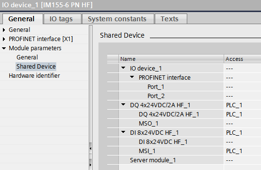
图. 15
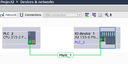
图. 16
在例子里S7-300 CPU管理输出模块的输出副本,也就是说 S7-300 可以访问输出模块的输出副本,因此对于 S7-300 来说输出模块是一个MSO模块。
S7-300访问输入模块的输入,因此对于S7-300来说输入模块是一个基本模块。
提供给S7-1500数据的模块或它们的副本不会分配给其他的IO控制器,
不要将接口模块分配给任何的IO控制器。
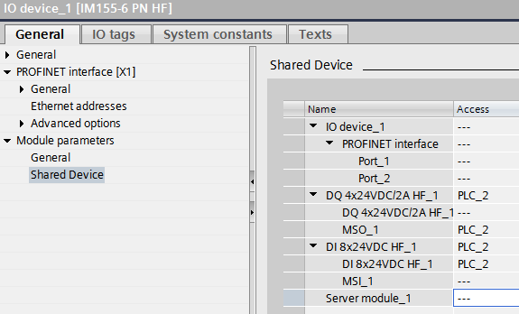
图. 17
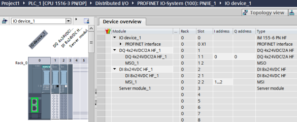
图. 18
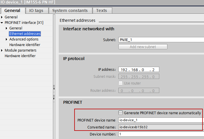
图. 19
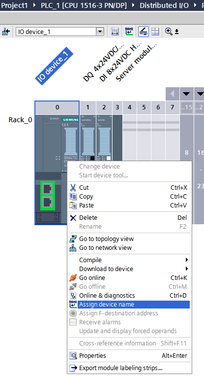
图. 20