长沙奈欧自动化设备有限公司专业销售西门子S7-200 / 300/400 / 1200PLC,数控系统,变频器,人机界面,触摸屏,伺服,电机,西门子电缆等,并可提供西门子维修服务,欢迎来电垂询
联系人: 刘文秀(销售经理)
24小时热线;137 6211 0473
QQ:1533714462
地址:长沙市岳麓区天顶街道尖山安置公寓楼702室
6ES7131-6BF01-0AA0西门子ET 200 6ES7131-6BF01-0AA0西门子ET 200 6ES7131-6BF01-0AA0西门子ET 200
数字量输出模块概览
数字量输入
订货号
CC 代码
基座单元类型
VPE
DI 16 x 24 V DC ST
6ES7131-6BH00-0BA0
CC00
A0
1
DI 16 x 24 V DC ST
6ES7131-6BH00-2BA0
CC00
A0
10
DI 8 x 24 V DC BA
6ES7131-6BF00-0AA0
CC01
A0
1
DI 8 x 24 V DC BA
6ES7131-6BF00-2AA0
CC01
A0
10
DI 8 x 24 V DC SRC BA
6ES7131-6BF60-0AA0
CC02
A0
1
DI 8 x 24 V DC ST
6ES7131-6BF00-0BA0
CC01
A0
1
DI 8 x 24 V DC ST
6ES7131-6BF00-2BA0
CC01
A0
10
DI 8 x 24 V DC HF
6ES7131-6BF00-0CA0
CC01
A0
1
DI 8 x NAMUR HF
6ES7131-6TF00-0CA0
CC01
A0
1
DI 8 x 24 V DC HS
三种操作方式:
6ES7131-6BF00-0DA0
CC01
A0
1
DI 4 x 120...230 V AC ST
6ES7131-6FD00-0BB1
CC41
B1
1
基座单元概述
基座单元
订货号
过程端子的 CC 代码
AUX 端子的 CC 代码
VPE
A0 型 BU
6ES7193-6BP20-0DA0
CC01 ~ CC05
CC71 ~ CC73
1
A0 型 BU
6ES7193-6BP20-2DA0
CC01 ~ CC05
CC71 ~ CC73
10
A0 型 BU
6ES7193-6BP00-0DA0
CC01 ~ CC05
--
1
A0 型 BU
6ES7193-6BP00-2DA0
CC01 ~ CC05
--
10
A0 型 BU
6ES7193-6BP20-0BA0
CC01 ~ CC05
CC71 ~ CC73
1
A0 型 BU
6ES7193-6BP20-2BA0
CC01 ~ CC05
CC71 ~ CC73
10
A0 型 BU
6ES7193-6BP00-0BA0
CC01 ~ CC05
--
1
A0 型 BU
6ES7193-6BP00-2BA0
CC01 ~ CC05
--
10
B1 型 BU
6ES7193-6BP20-0BB1
CC41
--
1
数字量输入模块包含用于 ET 200SP 的数字量输入。
可对模块进行热插拔,从而使设备极易维护。
提供有以下数字量输入模块:
对于单导线或多导线连接,提供了带有合适端子数的 BU。
一个浅色 BU 可以打开一个新负载组。传感器电源必须通过该 BU 馈入。接口模块旁的第一个 BU 必须为浅色 BU。
深色 BU 可通过自组装电压总线前馈左侧相邻的浅色 BU 的电源。因此,只有右侧下一个浅色 BU 需要新馈电。
与 I/O 模块的 BU 类型相对应的所有型号均可用作 BU。
BU 的端子处的电位通过 I/O 模块进行定义。端子的电位也可以通过模块特定的彩色编码标签对端子的电位进行标识,以避免接线错误。与相应 I/O 模块相匹配的彩色编码标签通过 I/O 模块的 CCxx 色码进行定义。该色码也印在模块的正面。颜色代码为 CC00 的模块不需要颜色编码标签。
在带有 10 个内置跨接 AUX 端子的 BU 中,这些端子也可以使用彩色编码标签进行标识。对于 10 个 AUX 端子,提供了红色、蓝色、黄色/绿色编码标签。
提供了两种不同材料的浅灰色和黄色标签条,用于为模块贴标签:
为了使电缆屏蔽线的连接能够节省空间和提高电磁兼容性,提供了可以快捷安装的屏蔽连接器。它包括一个屏蔽连接元件(可以插入到 BU 中)和一个可用于所有模块的屏蔽端子。用户无需任何附加接线即可实现功能性接地的低阻抗连接(DIN 导轨)。
Article number
6ES7131-6BF01-0AA0
6ES7131-6BF61-0AA0
6ES7131-6BF01-0BA0
6ES7131-6BH01-0BA0
ET 200SP, DI 8x 24V DC Basic, PU 1
ET 200SP, DI 8x 24V DC SRC BA
ET 200SP, DI 8x 24V DC ST, PU 1
ET 200SP, DI 16x 24V DC ST, PU 1
General inbation
Product type designation
DI 8x24 VDC BA
DI 8x24 VDC SRC BA
DI 8x24 VDC ST
DI 16x24 VDC ST
Firmware version
V0.0
V0.0
V0.0
V0.0
● FW update possible
No
No
No
No
usable BaseUnits
BU type A0
BU type A0
BU type A0
BU type A0
Color code for module-specific color identification plate
CC01
CC02
CC01
CC00
Product function
● I&M data
Yes; I&M0 to I&M3
Yes; I&M0 to I&M3
Yes; I&M0 to I&M3
Yes; I&M0 to I&M3
Engineering with
● STEP 7 TIA Portal configurable/integrated as of version
V14
V14
V14
V14
● STEP 7 configurable/integrated as of version
V5.5 SP3 / -
V5.5 SP3 / -
V5.5 SP3 or higher
V5.5 SP3
● PCS 7 configurable/integrated as of version
V8.1 SP1
V8.1 SP1
● PROFIBUS as of GSD version/GSD revision
One GSD file each, Revision 3 and 5 and higher
One GSD file each, Revision 3 and 5 and higher
One GSD file each, Revision 3 and 5 and higher
One GSD file each, Revision 3 and 5 and higher
● PROFINET as of GSD version/GSD revision
GSDML V2.3
GSDML V2.3
GSDML V2.3
GSDML V2.3
Operating mode
● DI
Yes
Yes
Yes
Yes
● Counter
No
No
No
No
● Oversampling
No
No
No
No
● MSI
No
No
No
No
Supply voltage
Rated value (DC)
24 V
24 V
24 V
24 V
permissible range, lower limit (DC)
19.2 V
19.2 V
19.2 V
19.2 V
permissible range, upper limit (DC)
28.8 V
28.8 V
28.8 V
28.8 V
Reverse polarity protection
Yes
Yes
Yes
Yes
Input current
Current consumption, max.
70 mA; All channels are supplied from the encoder supply
50 mA; All channels are supplied from the encoder supply
90 mA
Encoder supply
Number of outputs
8
8
Output voltage encoder supply, min.
19.2 V
19.2 V
Short-circuit protection
Yes; per module
No
Yes; per module
24 V encoder supply
● 24 V
Yes
Yes
No
● Short-circuit protection
Yes
Yes
● Output current, max.
700 mA; Total current of all encoders
Power loss
Power loss, typ.
1.6 W; 24 V, 8 bs supplied via encoder supply
1.5 W
1 W; 24 V, 8 bs supplied via encoder supply
1.7 W
Address area
Address space per module
● Inputs
1 byte
1 byte
1 byte; + 1 byte for QI inbation
2 byte; + 2 bytes for QI inbation
Hardware configuration
Automatic encoding
Yes
Yes
Yes
Yes
● Mechanical coding element
Yes
Yes
Yes
Submodules
● Number of configurable submodules, max.
4
4
Selection of BaseUnit for connection variants
● 1-wire connection
BU type A0
BU type A0
BU type A0
BU type A0
● 2-wire connection
BU type A0
BU type A0
BU type A0
BU type A0 + Potential isolation module
● 3-wire connection
BU type A0 with AUX terminals
BU type A0 with AUX terminals
BU type A0 with AUX terminals
BU type A0 + Potential isolation module
● 4-wire connection
BU type A0 + Potential isolation module
BU type A0 + Potential isolation module
BU type A0 + Potential isolation module
BU type A0 + Potential isolation module
Digital bs
Number of digital bs
8
8
8
16
Digital bs, beterizable
Yes
Yes
Yes
Yes
Source/sink b
P-reading
m-reading
P-reading
P-reading
Input characteristic curve in accordance with IEC 61131, type 1
Yes
Input characteristic curve in accordance with IEC 61131, type 2
Yes
Input characteristic curve in accordance with IEC 61131, type 3
Yes
Yes
Input voltage
● Type of b voltage
DC
DC
DC
DC
● Rated value (DC)
24 V
24 V
24 V
24 V
● for signal "0"
-30 to +5V
30 V to -5 V (reference potential is L+)
-30 to +5V
-30 to +5V
● for signal "1"
+11 to +30V
-11 V to -30 V (reference potential is L+)
+11 to +30V
+11 to +30V
Input current
● for signal "1", typ.
6.8 mA
6 mA
2.5 mA
2.5 mA
Input delay (for rated value of b voltage)
for standard bs
— beterizable
Yes; 0.05 / 0.1 / 0.4 / 0.8 / 1.6 / 3.2 / 12.8 / 20 ms (in each case + delay of 30 to 500 µs, depending on line length)
Yes; 0.05 / 0.1 / 0.4 / 0.8 / 1.6 / 3.2 / 12.8 / 20 ms (in each case + delay of 30 to 500 µs, depending on line length)
Yes; 0.05 / 0.1 / 0.4 / 0.8 / 1.6 / 3.2 / 12.8 / 20 ms (in each case + delay of 30 to 500 µs, depending on line length)
Yes; 0.05 / 0.1 / 0.4 / 0.8 / 1.6 / 3.2 / 12.8 / 20 ms (in each case + delay of 30 to 500 µs, depending on line length)
— at "0" to "1", min.
0.05 ms
0.05 ms
0.05 ms
0.05 ms
— at "0" to "1", max.
20 ms
20 ms
20 ms
20 ms
— at "1" to "0", min.
0.05 ms
0.05 ms
0.05 ms
0.05 ms
— at "1" to "0", max.
20 ms
20 ms
20 ms
20 ms
Cable length
● shielded, max.
1 000 m
1 000 m
1 000 m
1 000 m
● unshielded, max.
600 m
200 m
600 m
600 m
Encoder
Connectable encoders
● 2-wire sensor
Yes
Yes
Yes
Yes
— permissible quiescent current (2-wire sensor), max.
2 mA
1.5 mA
1.5 mA
1.5 mA
Isochronous mode
Isochronous operation (application synchronized up to terminal)
No
No
No
No
Interrupts/diagnostics/status inbation
Diagnostics function
Yes
Yes
Yes
Yes
Alarms
● Diagnostic alarm
Yes
Yes
Yes
Yes
Diagnostic messages
● Diagnostic inbation readable
Yes
Yes
Yes
Yes
● Monitoring the supply voltage
Yes
Yes
Yes
Yes
— beterizable
Yes
Yes
Yes
Yes
● Monitoring of encoder power supply
No
No
Yes; Module-by-module, optional protective circuit for preventing wire-break diagnostics in the case of simple encoder contacts: 25 kOhm to 45 kOhm
No
● Wire-break
No
No
Yes; Module-wise
Yes; Module-by-module, optional protective circuit for preventing wire-break diagnostics in the case of simple encoder contacts: 25 kOhm to 45 kOhm
● Short-circuit
No
No
Yes; Module-wise
No
● Group error
Yes
Diagnostics indication LED
● Monitoring of the supply voltage (PWR-LED)
Yes; green PWR LED
Yes; green PWR LED
Yes; green PWR LED
Yes; green PWR LED
● Channel status display
Yes; Green LED
Yes; Green LED
Yes; Green LED
Yes; Green LED
● for channel diagnostics
No
No
No
No
● for module diagnostics
Yes; green/red DIAG LED
Yes; green/red DIAG LED
Yes; green/red DIAG LED
Yes; green/red DIAG LED
Potential separation
Potential separation channels
● between the channels
No
No
No
No
● between the channels and backplane bus
Yes
Yes
Yes
Yes
● between the channels and the power supply of the electronics
No
No
No
No
Isolation
Isolation tested with
707 V DC (type test)
707 V DC (type test)
707 V DC (type test)
707 V DC (type test)
Ambient conditions
Ambient temperature during operation
● horizontal installation, min.
0 °C
0 °C
0 °C
● horizontal installation, max.
60 °C
60 °C
60 °C
● vertical installation, min.
0 °C
0 °C
0 °C
● vertical installation, max.
50 °C
50 °C
50 °C
Altitude during operation relating to sea level
● Ambient air temperature-barometric pressure-altitude
On request: Ambient temperatures lower than 0 °C (without condensation) and/or installation altitudes greater than 2 000 m
On request: Ambient temperatures lower than 0 °C (without condensation) and/or installation altitudes greater than 2 000 m
On request: Ambient temperatures lower than 0 °C (without condensation) and/or installation altitudes greater than 2 000 m
On request: Ambient temperatures lower than 0 °C (without condensation) and/or installation altitudes greater than 2 000 m
Dimensions
Width
15 mm
15 mm
15 mm
15 mm
Height
73 mm
73 mm
73 mm
73 mm
Depth
58 mm
58 mm
58 mm
58 mm
Weights
Weight, approx.
28 g
28 g
28 g
28 g
Article number
6ES7131-6BF00-0CA0
6ES7131-6BF00-0DA0
6ES7131-6TF00-0CA0
6ES7131-6FD01-0BB1
ET 200SP, DI 8X24VDC HF
ET 200SP, DI 8X24VDC HIGH SPEED
ET 200SP, DI 8XNAMUR HF
ET 200SP, DI 4x 120..230VvAC ST
General inbation
Product type designation
DI 8x24 V DC HF
DI 8x24 V DC HS
DI 8xNAMUR HF
DI 4x120 … 230 V AC ST
Firmware version
V2.0
V1.0.2
V1.0
V0.0
● FW update possible
Yes
Yes
Yes
No
usable BaseUnits
BU type A0
BU type A0
BU type A0
BU type B1
Color code for module-specific color identification plate
CC01
CC01
CC01
CC41
Product function
● I&M data
Yes; I&M0 to I&M3
Yes; I&M0 to I&M3
Yes; I&M0 to I&M3
Yes; I&M0 to I&M3
Engineering with
● STEP 7 TIA Portal configurable/integrated as of version
V13 SP1 / -
V13 SP1
V13 / V13
V14
● STEP 7 configurable/integrated as of version
V5.5 / -
V5.5 SP3 / -
V5.5 SP3 / -
V5.5 SP3
● PCS 7 configurable/integrated as of version
V8.1 SP1
● PROFIBUS as of GSD version/GSD revision
One GSD file each, Revision 3 and 5 and higher
GSD Revision 5
GSD Revision 5
One GSD file each, Revision 3 and 5 and higher
● PROFINET as of GSD version/GSD revision
GSDML V2.3
GSDML V2.3
GSDML V2.3
GSDML V2.3
Operating mode
● DI
Yes
Yes
Yes
Yes
● Counter
No
Yes
No
No
● Oversampling
No
Yes
No
No
● MSI
Yes
No
No
No
Supply voltage
Rated value (DC)
24 V
24 V
24 V
permissible range, lower limit (DC)
19.2 V
19.2 V
19.2 V
permissible range, upper limit (DC)
28.8 V
28.8 V
28.8 V
Rated value (AC)
230 V
Reverse polarity protection
Yes
Yes
Yes
No
Input current
Current consumption (rated value)
10 mA
Current consumption, max.
70 mA; without sensor supply
Encoder supply
Number of outputs
8
8
4
Output voltage encoder supply, min.
19.2 V
Short-circuit protection
Yes
Yes
No; when using BU type B1, a fuse with 10 A tripping current must be provided
Output current
● up to 60 °C, max.
10 A
24 V encoder supply
● 24 V
Yes
Yes
No
● Short-circuit protection
Yes; per channel, electronic
Yes; per module, electronic
No
● Output current, max.
700 mA
Power loss
Power loss, typ.
1.5 W; 24 V, 8 bs supplied via encoder supply
1.5 W
1.5 W
1 W; Active power, load voltage 230 V, all bs connected with 230 V, 50 Hz
Address area
Address space per module
● Address space per module, max.
45 byte
1 byte; + 1 byte for QI inbation
● Inputs
1 byte; + 1 byte for QI inbation
32 byte; 1 byte + 1 byte for QI inbation in DI mode; 32 bytes in Oversampling mode; 25 bytes in Counter mode
1 byte; + 1 byte for QI inbation
● Outputs
20 byte; In count mode
Hardware configuration
Automatic encoding
Yes
Yes
● Mechanical coding element
Yes
Yes
Submodules
● Number of configurable submodules, max.
4
Selection of BaseUnit for connection variants
● 1-wire connection
BU type A0
BU type A0
BU type A0
BU type B1
● 2-wire connection
BU type A0
BU type A0
BU type A0
BU type B1
● 3-wire connection
BU type A0 with AUX terminals
BU type A0 with AUX terminals
BU type A0 + external terminals
BU type B1
● 4-wire connection
BU type A0 + Potential isolation module
BU type A0 + external terminals
BU type A0 + external terminals
BU type B1 + potential distributor module
Digital bs
Number of digital bs
8
8
8; NAMUR
4
Digital bs, beterizable
Yes
Yes
Source/sink b
P-reading
P-reading
Input characteristic curve in accordance with IEC 61131, type 3
Yes
Yes
Pulse extension
Yes; Pulse duration from 4 µs
Yes
Yes; 0.5 s, 1 s, 2 s
● Length
2 s; 50 ms, 100 ms, 200 ms, 500 ms, 1 s, 2 s
2 s; 50 ms, 100 ms, 200 ms, 500 ms, 1 s, 2 s
Edge buation
Yes; rising edge, falling edge, edge change
Yes; rising edge, falling edge, edge change
Signal change flutter
Yes; 2 to 32 signal changes
Flutter observation b
Yes; 0.5 s, 1 s to 100 s in 1-s steps
Digital b functions, beterizable
● Gate start/stop
Yes
● Freely usable digital b
Yes
● Counter
Yes
— Number, max.
4
— Counting frequency, max.
10 kHz
— Counting b
32 bit
— Counting direction up/down
Yes
● Digital b with oversampling
Yes
— Number, max.
8
— Values per cycle, max.
32
— Resolution, min.
7.8125 µs
Input voltage
● Type of b voltage
DC
DC
DC
120/230 V AC (47 Hz to 63 Hz)
● Rated value (DC)
24 V
24 V
8.2 V
● Rated value (AC)
230 V
● for signal "0"
-30 to +5V
-30 to +5V
0V AC to 40V AC
● for signal "1"
+11 to +30V
+11 to +30V
74 V AC to 264 V AC
Input current
● for signal "1", typ.
2.5 mA
6 mA
10.8 mA
for 10 k switched contact
— for signal "0"
0.35 to 1.2 mA
— for signal "1"
2.1 to 7 mA
for unswitched contact
— for signal "0", max. (permissible quiescent current)
0.5 mA
— for signal "1"
typ. 8 mA
for NAMUR encoders
— for signal "0"
0.35 to 1.2 mA
— for signal "1"
2.1 to 7 mA
Input delay (for rated value of b voltage)
● tolerated changeover time for changeover contacts
300 ms
for standard bs
— beterizable
Yes; 0.05 / 0.1 / 0.4 / 0.8 / 1.6 / 3.2 / 12.8 / 20 ms (in each case + delay of 30 to 500 µs, depending on line length)
Yes; none / 0.05 / 0.1 / 0.4 / 0.8 / 1.6 / 3.2 / 12.8 / 20 ms
No
No
— at "0" to "1", min.
0.05 ms
1.5 ms
— at "0" to "1", max.
20 ms
4 ms
— at "1" to "0", min.
0.05 ms
10 ms
— at "1" to "0", max.
20 ms
10 ms
for interrupt bs
— beterizable
Yes
for counter/technological functions
— beterizable
Yes
for NAMUR bs
— at "0" to "1", max.
12 ms
— at "1" to "0", max.
12 ms
Cable length
● shielded, max.
1 000 m
50 m
200 m
1 000 m
● unshielded, max.
600 m
50 m
600 m
Encoder
Connectable encoders
● NAMUR encoder/changeover contact according to EN 60947
Yes
● Single contact / changeover contact unconnected
Yes
● Single contact / changeover contact connected with 10 kΩ
Yes
● 2-wire sensor
Yes
Yes
Yes
— permissible quiescent current (2-wire sensor), max.
1.5 mA
1.5 mA
Isochronous mode
Isochronous operation (application synchronized up to terminal)
Yes
Yes
No
No
Filtering and processing time (TCI), min.
420 µs
Bus cycle time (TDP), min.
500 µs
125 µs
Jitter, max.
8 µs
5 µs
Interrupts/diagnostics/status inbation
Diagnostics function
Yes
Yes
Yes
Alarms
● Diagnostic alarm
Yes; channel by channel
Yes
Yes; channel by channel
No
● Hardware interrupt
Yes; Parameterizable, channels 0 to 7
Yes
Yes; Parameterizable, channels 0 to 7
No
Diagnostic messages
● Diagnostic inbation readable
Yes
Yes
Yes
● Monitoring the supply voltage
Yes
Yes
Yes
No
— beterizable
Yes
Yes
Yes
● Monitoring of encoder power supply
Yes; channel by channel
Yes; Module-wise
Yes; channel by channel
● Wire-break
Yes; Channel by channel, optional protective circuit for preventing wire-break diagnostics in the case of simple encoder contacts: 25 kOhm to 45 kOhm
No
Yes; channel by channel
No
● Short-circuit
Yes; channel by channel
Yes; Module-wise
Yes; channel by channel
No
● Group error
Yes
Diagnostics indication LED
● Monitoring of the supply voltage (PWR-LED)
Yes; green PWR LED
Yes; green PWR LED
Yes; green PWR LED
Yes; green PWR LED
● Channel status display
Yes; Green LED
Yes; Green LED
Yes; Green LED
Yes; Green LED
● for channel diagnostics
Yes; Red LED
No
Yes; Red LED
No
● for module diagnostics
Yes; green/red DIAG LED
Yes; green/red DIAG LED
Yes; green/red DIAG LED
Yes; green/red DIAG LED
Potential separation
Potential separation channels
● between the channels
No
No
No
No
● between the channels and backplane bus
Yes
Yes
Yes
Yes
● between the channels and the power supply of the electronics
No
No
Yes
No
Isolation
Isolation tested with
707 V DC (type test)
707 V DC (type test)
707 V DC (type test)
2 545 V DC/2 s (routine test)
Ambient conditions
Ambient temperature during operation
● horizontal installation, min.
0 °C
● horizontal installation, max.
60 °C
● vertical installation, min.
0 °C
● vertical installation, max.
50 °C
Altitude during operation relating to sea level
● Ambient air temperature-barometric pressure-altitude
On request: Negative ambient temperature down to -30 °C (without condensation), installation altitudes between 2 000 m and 5 000 m
On request: Ambient temperatures lower than 0 °C (without condensation) and/or installation altitudes greater than 2 000 m
Dimensions
Width
15 mm
15 mm
15 mm
20 mm
Height
73 mm
73 mm
73 mm
73 mm
Depth
58 mm
58 mm
58 mm
58 mm
Weights
Weight, approx.
28 g
28 g
32 g
36 g
固件版本为V1.0或更高的"TM Count 1x24V" 和 "TM PosInput 1" 模块可以在以下ET 200SP接口模块下使用:
工艺模块支持以下列出的操作模式:
注意
警告
该常问问题仅适用于 STEP 7 (TIA Portal) V13 以及更高版本,因为版本低于 V13 的STEP7 的工艺对象是无法使用的。
目录:
1 问题
1 问题
Normal 0 false false false false EN-US ZH-CN X-NONE
序号
说明与图示
1.
内部风冷
驱动组件中电子单元和功率单元产生的功率损耗通过自然冷却或强制通风系统排散到控制柜内部
2.
外部风冷
采用“穿孔”技术,系统组件中功率单元的散热器穿过控制柜内的安装面。因此可以将电力电路的热损耗释放到一个单独的外部冷却回路上,柜内残留的热损耗由电子元件产生。这种外部散热器可以达到IP54防护等级。散热器配有散热片和风扇(属于供货范围),向后伸出一个单独的通风管道,该管道也可以向外打开。
3.
冷却板式冷却
采用冷却板式冷却的单元可以将功率单元的热损耗通过单元后面板上的导热介质传导到一个外部散热器上。例如,外部散热器可采用水冷。
4.
液体冷却
在液冷单元,功率半导体安装在冷却介质流经的散热器上,该单元产生的大部分热量会被冷却介质吸收并可在控制柜外耗散。
以下手册中介绍了模块共享输入/输出(MSI/MSO)的基本信息。 SIMATIC PROFINET PROFINET with STEP 7 V13.
条目 ID 102325771包含了支持MSI/MSO功能的IO设备的概览。
这篇文档介绍了如何在STEP 7 (TIA Portal)中配置访问共享的设备及模块内部共享输入/输出功能。可以在两个不同的项目里或同一个项目里来配置IO 控制器。
按照以下步骤在同一个项目下配置两个CPU:
按照以下步骤在两个不同的项目下配置两个CPU:

列表价(不含增值税)
显示价格
您的单价(不含增值税)
显示价格
PDF 格式的数据表
下载
服务和支持 (手册,认证,问答...)
下载
产品
商品编号(市售编号)
6ES7131-6BF01-0AA0
产品说明
SIMATIC ET 200SP, Digital b module, DI 8x 24V DC Basic, type 2 (IEC 61131), sink b, (PNP, P-reading), Packing unit: 1 piece, fits to BU-type A0, Colour Code CC01, b delay time 0,05..20ms, module diagnostics for: supply voltage
产品家族
数字量输入模块
产品生命周期 (PLM)
PM300:有效产品
价格数据
价格组 / 总部价格组
IR / 255
列表价(不含增值税)
显示价格
您的单价(不含增值税)
显示价格
金属系数
无
交付信息
出口管制规定
AL : N / ECCN : EAR99H
工厂生产时间
25 天
净重 (Kg)
0.04 Kg
产品尺寸 (W x L X H)
未提供
包装尺寸
7.00 x 7.80 x 2.50
包装尺寸单位的测量
CM
数量单位
1 件
包装数量
1
其他产品信息
EAN
4047623408673
UPC
804766528071
商品代码
85389091
LKZ_FDB/ CatalogID
ST76
产品组
4520
原产国
德国
Compliance with the substance restrictions according to RoHS directive
RoHS 合规开始日期: 2017.09.15
产品类别
A: 问题无关,即刻重复使用
电气和电子设备使用后的收回义务类别
没有电气和电子设备使用后回收的义务
分类
版本
分类
eClass
5.1
27-24-26-04
eClass
6
27-24-26-04
eClass
7.1
27-24-26-04
eClass
8
27-24-26-04
eClass
9
27-24-26-04
eClass
9.1
27-24-26-04
ETIM
5
EC001599
ETIM
6
EC001599
IDEA
4
3566
UNSPSC
15
32-15-17-05

![]() 6ES7193-6BP00-0BA0
6ES7193-6BP00-0BA0

![]() 6ES7193-6BP00-0DA0
6ES7193-6BP00-0DA0

![]() 6ES7132-6BF01-0AA0
6ES7132-6BF01-0AA0

![]() 6ES7131-6BH01-0BA0
6ES7131-6BH01-0BA0

![]() 6AV2123-2GB03-0AX0
6AV2123-2GB03-0AX0
概述
![]()
应用
![]()
设计
可用 BU
端子的颜色标识
标记
系统内置屏蔽连接
![]()
技术规范
哪些接口模块和ET 200SP的CPU可以使用 "TM Count 1x24V" 和 "TM PosInput 1" 模块?
S120 书本型模块有哪些冷却方式
2 回答
S120 书本型模块有哪些冷却方式?
2 回答
SINAMICS S120 书本型模块提供了以下几种不同冷却方式的订货形式:
(1) 内部风冷
(2) 外部风冷
(3) 冷却板式冷却
(4) 液体冷却
各种冷却方式的详细说明如表1所示。


如何在STEP 7 (TIA Portal)中配置访问共享的设备及模块内部共享输入/输出(MSI/MSO)功能?
在这个例子里,一个S7-1500 CPU和一个S7-300 CPU作为IO控制器来访问作为共享设备的ET200SP的输入和输出数据。
一个输入模块和一个输出模块插到ET200SP的插槽中,S7-1500CPU将会读取输入和写入输出,S7-300CPU将会读取输入和输出。

图. 1
在同一个项目下的配置

图. 2

图. 3

图. 4
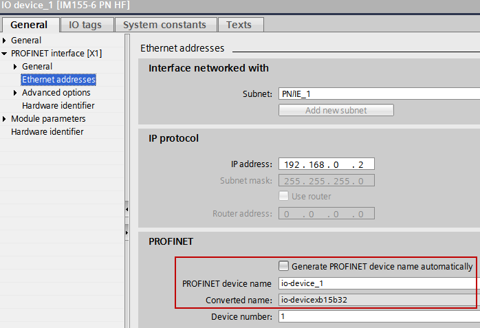
图. 5
在例子里S7-1500CPU会被设置为输出,也就是说S7-1500(PLC1)可以访问输出模块的输出,因此对于S7-1500来说输出模块是一个基本模块。因此对于S7-1500来说输入模块是一个MSI模块。
提供给S7-300 (PLC_2)数据的模块或它们的副本不会分配给其他的IO控制器,不要将接口模块分配给任何的IO控制器。
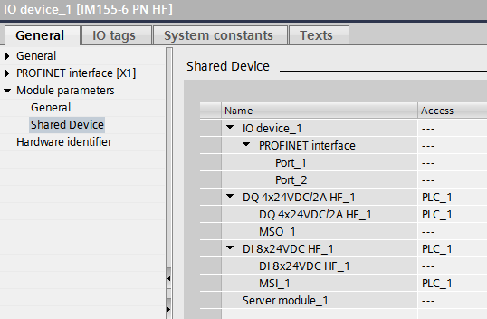
图. 6
在例子里S7-300CPU管理输出模块的输出副本,也就是说S7-300(PLC2)可以访问输出模块的输出副本,因此对于S7-300来说输出模块是一个MSO模块。
S7-300(PLC2)访问输入模块的输入,因此对于S7-300来说输入模块是一个基本模块。
提供给S7-1500 (PLC_1)数据的模块或它们的副本不会分配给其他的IO控制器,
不要将接口模块分配给任何的IO控制器。
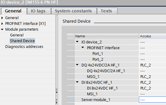
图. 7
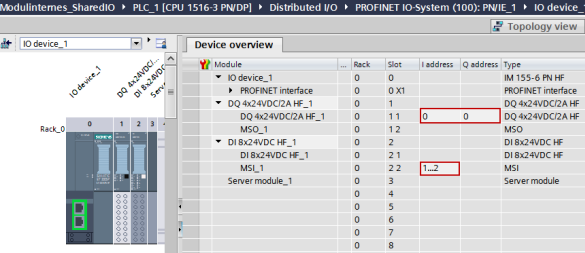
图. 8
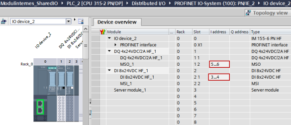
图. 9
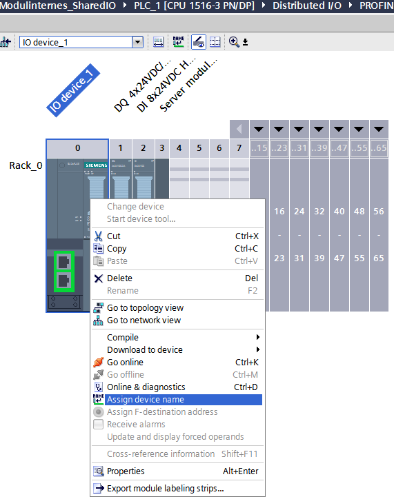
图. 10
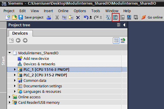
图. 11
在两个不同项目下的配置
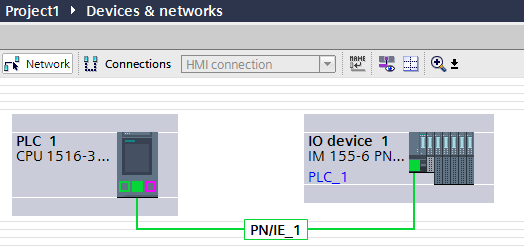
图. 12
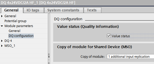
图. 13
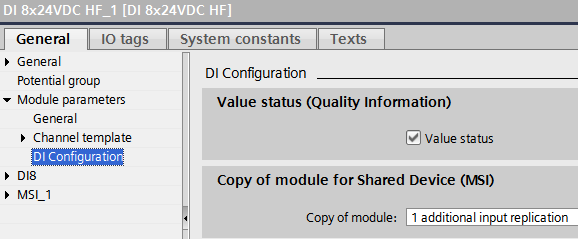
图. 14
在例子里 S7-1500CPU 会被设置为输出,也就是说S7-1500可以访问输出模块的输出,因此对于S7-1500来说输出模块是一个基本模块。
S7-1500访问输入模块的输入副本,因此对于S7-1500来说输入模块是一个MSI模块。
提供给S7-300数据的模块或它们的副本不会分配给其他的IO控制器。
不要将接口模块分配给任何的IO控制器。
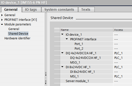
图. 15
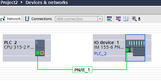
图. 16
在例子里S7-300 CPU管理输出模块的输出副本,也就是说 S7-300 可以访问输出模块的输出副本,因此对于 S7-300 来说输出模块是一个MSO模块。
S7-300访问输入模块的输入,因此对于S7-300来说输入模块是一个基本模块。
提供给S7-1500数据的模块或它们的副本不会分配给其他的IO控制器,
不要将接口模块分配给任何的IO控制器。
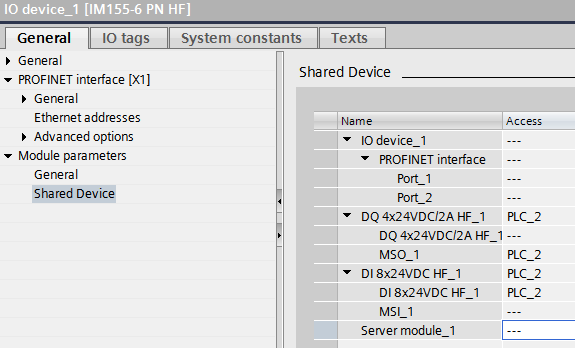
图. 17
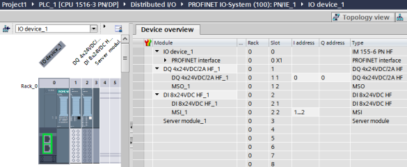
图. 18
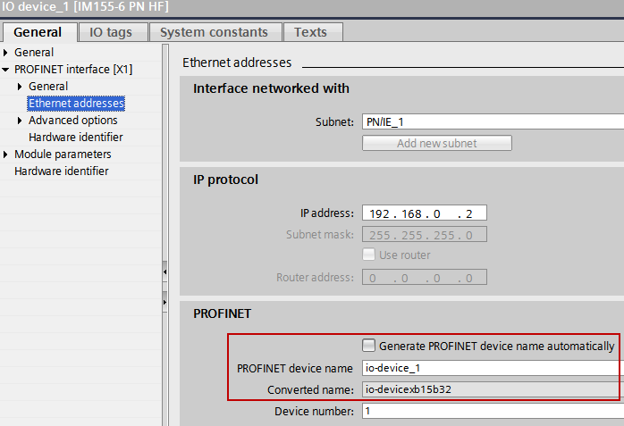
图. 19
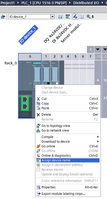
图. 20